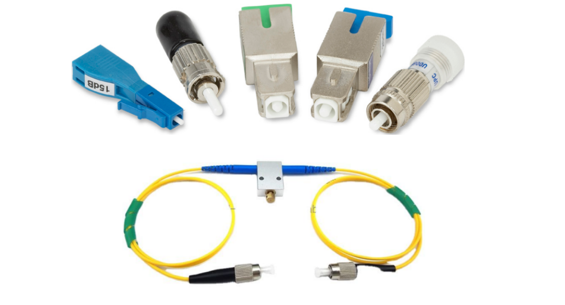
Optical Attenuator: A Key Technology for Optical Signal Control
Optical Attenuator: A Key Technology for Optical Signal Control
Overview of Optical Attenuator
An Optical Attenuator is a device used to reduce the intensity of optical signals. It is widely applied in fiber optic communications, laser systems, and other optical applications. Its primary function is to control the strength of light to prevent signal overload, which can lead to system damage or distortion.
Applications:
Optical communication lines, system evaluation, research
Optical communication lines, system adjustment, correction
Used to adjust the strength of each channel signal in wavelength division multiplexing optical fiber network
Test the optical power attenuation of instruments
Power flatness of optical amplifiers
Simulate long-distance optical fiber transmission
Detect the dynamic range of the transmission system.
Optical Attenuator Type
Displacement optical attenuator: lateral displacement coupler, longitudinal displacement coupler
Attenuation sheet attenuator
Liquid crystal optical attenuator
Only used for fixed attenuators, large return loss, polarization-independent bulk devices


The loss after lateral misalignment is then


The range of displacement determines that it is not a variable optical attenuator, but only a fixed optical attenuator, and is welded or bonded.
The return loss is very high, greater than 60dB.
Used for fixed attenuators and some small adjustable optical attenuators
Polarization-independent bulk devices


 S-Ls curve


Its attenuation component has been changed accordingly. It is composed of a step attenuator and a continuously variable attenuator. The attenuation of the step attenuator is 0, 10, 20, 30, 40, 50dB, and the attenuation of the continuously variable attenuator is 0-15dB. Therefore, the total attenuation adjustment range is: 0-65dB. In this way, through the combined effect of coarse and fine gears, the purpose of continuously attenuating light energy can be achieved.


When a certain voltage is applied to the two electrodes of the liquid crystal, the twisted arrangement of the liquid crystal crystal direction produces a certain angle of deflection, so that the part of the liquid crystal. o light and e light, the polarization plane rotates. Among them, the part of the polarization direction rotated 90 degrees. o light and e light are combined by the beam splitter P1 into a beam of parallel light for emission, and the remaining polarized light cannot be combined and is emitted at a certain angle.

Attenuation and insertion loss
Coupling of fiber and self-focusing (GRIN) lens

It is used to test the power of light, expressed in dBm or mW.
Generally, the intensity of LD light source is between -4dBm ~ -10dBm.
The intensity of LED is between -20dBm ~ -30dBm.
The attenuation of the attenuation chip optical attenuator depends on the transmittance and uniformity of the metal evaporated film layer. According to the Bragg law, the transmittance depends on the internal transmittance of the absorbing material and its thickness.
Return loss
The return loss of an optical attenuator refers to the ratio of the light energy incident into the optical attenuator to the light energy reflected from the attenuator along the incident light path. The return loss of a high-performance optical attenuator is above 40dB.

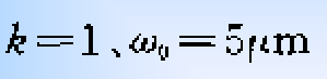
n0 is the refractive index of air;
n1 is the refractive index of the fiber core;
w is the mode field radius of the fiber;
A is the self-focusing constant.
The mode field radius after the light is emitted from the lens:


How to choose a fiber optic attenuator?
Related Article