
Cannot be ignored optical isolator: improving the quality of optical signals
author: Jocelin
2024-11-12
Function
Optical isolator is a passive magneto-optical device that only allows light to be transmitted in a single direction. Optical isolators are used to prevent adverse effects on light sources caused by back reflections or signals. Backreflection may damage the laser or cause mode hopping, amplitude changes, or frequency shifts. In high-power applications, back reflection can also cause instability and power spikes.
The working principle of an isolator is based on the Faraday effect. In 1842, Faraday discovered that polarized light would rotate when passing through glass (or other materials) in a magnetic field. The direction of rotation depends on the direction of the magnetic field rather than the direction of light propagation. Therefore, rotation is non reciprocal. The rotation factor Q is equal to V x L x H, where V, L, and H are defined as follows.
The working principle of an isolator is based on the Faraday effect. In 1842, Faraday discovered that polarized light would rotate when passing through glass (or other materials) in a magnetic field. The direction of rotation depends on the direction of the magnetic field rather than the direction of light propagation. Therefore, rotation is non reciprocal. The rotation factor Q is equal to V x L x H, where V, L, and H are defined as follows.
Faraday rotation
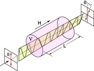
Q = V x L x H
V: Field constant, a property of optical materials, measured in minutes per Oersted centimeter.
L: The optical path length through optical materials, measured in cm.
H: Magnetic field strength, measured in Oersted.
L: The optical path length through optical materials, measured in cm.
H: Magnetic field strength, measured in Oersted.
The optical isolator consists of an incident polarizer, a Faraday rotator, and an outgoing polarizer. The incident polarizer, as a filter, only allows linearly polarized light to enter the Faraday rotator. The Faraday rotator rotates linearly polarized light by 45 degrees, and then the light passes through the exit polarizer. At this point, the polarization direction of the output light has rotated by 45 degrees relative to the incident light. In the reverse optical path, the Faraday rotator continues to rotate the polarization of light in the same direction as in the forward optical path, so the polarization of light at this point is rotated 90 degrees relative to the incident light. The polarization of this light is perpendicular to the propagation axis of the incident polarizer, so depending on the type of polarizer, energy will be reflected or absorbed.
Polarization related isolator
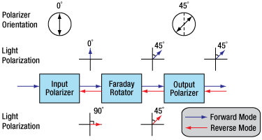
Figure 2 Polarization related isolator. The reverse transmission light is blocked by the incident polarizer.
Positive mode
In this example, it is assumed that the axis of the incident polarizer is perpendicular (indicated by 0 ° in Figure 2). Both polarized and unpolarized light become vertically polarized light after passing through an incident polarizer. The Faraday rotator rotates the polarization plane (POP) by 45 degrees in the forward direction. Finally, the light passes through an output polarizer with an axial angle of 45 °. Therefore, the polarization plane of light passing through the isolator is 45 °.
Reverse mode
The light passing through the isolator in reverse first enters through the output polarizer, making the polarization direction of the light 45 ° relative to the incident polarizer. Then enter the Faraday rotator, and the polarization plane continues to rotate at a positive angle of 45 °. At this point, the relative incident polarizer has rotated 90 degrees, so the polarization plane is perpendicular to the propagation axis of the incident polarizer. So, light will be reflected or absorbed.
Polarization Insensitive Fiber Isolator
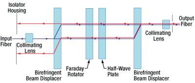
Figure 3 Polarization independent optical isolator. The light deviates from the input path and is blocked by the casing.
Positive mode
For polarization independent fiber isolators, the incident light is split into two beams by a birefringent crystal (as shown in Figure 3). The Faraday rotator and half wave plate rotate the polarization direction of the two beams continuously by 45 degrees, and then the two beams pass through the second birefringent crystal and merge again.
Reverse mode
After passing through the second birefringent crystal, the reflected light is split into two beams, with the same polarization as the forward mode light. Due to the fact that the Faraday rotator is a non reciprocal polarization rotator, it will counteract the polarization rotation of the reverse mode light generated by the half wave plate. When these two beams of light pass through the first birefringent crystal, they will deviate from the collimating lens and be absorbed by the outer shell wall, thereby preventing the reverse mode from entering the incident fiber.
Essential information
Magnet
The magnet is the main factor determining the size and performance of the isolator. The size of a magnet is not only determined by the magnetic field strength, but also influenced by mechanical design. Not using a single magnet but through complex assembly. The modeling system has optimized and simulated many parameters that affect size, optical path length, rotation, and magnetic field uniformity. Due to the strong magnetic field around the isolator, please do not place iron or magnetic objects within 5 cm of the isolator.
Temperature
Both magnets and Faraday rotator are closely related to temperature. The magnetic field strength and Field constant decrease with increasing temperature. If the experimental environment exceeds the range of room temperature ± 10 ° C, please contact technical support.
Pulse dispersion
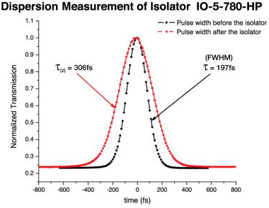
Laser pulses will generate pulse broadening when passing through materials with a refractive index greater than 1. The smaller the pulse width, the greater the dispersion, so for ultrafast lasers, dispersion may become very significant.
τ: Pulse width before passing through the isolator
τ ((z)): Pulse width after passing through the isolator
example:
When τ=197 fs, τ ((z))=306 fs (as shown in Figure 4)


Fiber optic isolator: the "one-way valve" for optical communication
Optical Isolators: A Fusion of Technological Innovation and Cost-Effectiveness
Related Article


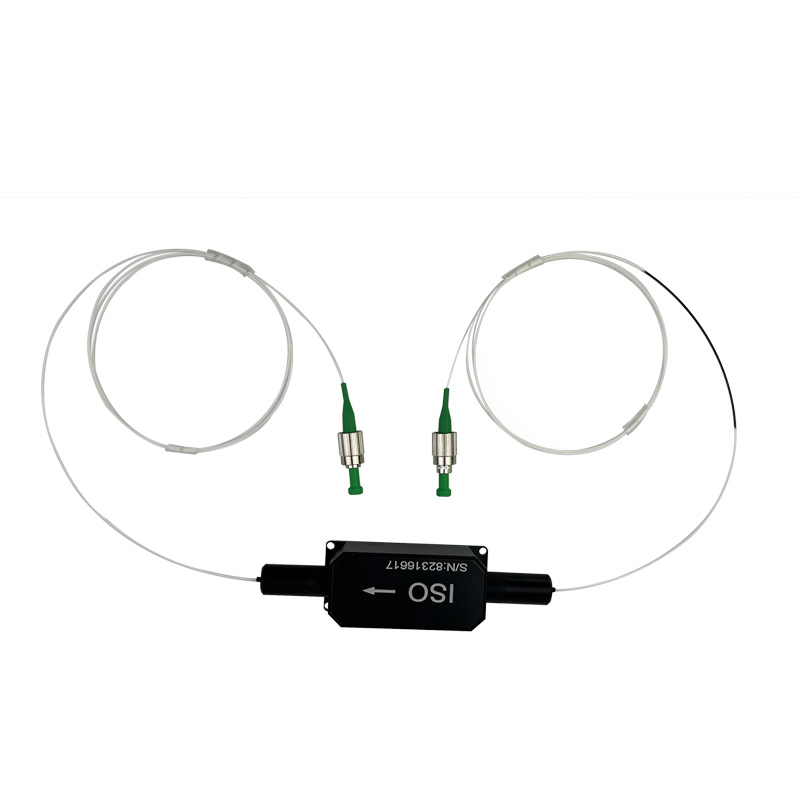
In the era of rapidly advancing fiber optic communications and laser technology, optical isolators have become an essential component in optical communication systems. Known as passive optical non-reciprocal devices, optical isolators are designed to eliminate or suppress the back reflection of light in fiber optic channels, thereby enhancing system stability and reliability.
Optical Isolators: A Fusion of Technological Innovation and Cost-Effectiveness