
What is FBT coupler, do you know it ?
author: Jocelin
2024-09-27
FBT Coupler
Fusion tapered fiber coupler (FBT coupler) is a type of optical passive device that can couple optical signals in a special structural coupling region during transmission and redistribute them. In the early days, it was often used to extract a certain amount of power from transmission channels for monitoring purposes. With the rapid development of fiber optic technology, fiber couplers have gradually developed multiple coupling types such as 1 × 2, 1 × 4, 1 × 8, or 2 × 2, 4 × 4, as well as various coupling ratios for application.
What are its characteristics?
1. Divide a beam of light into two or more beams according to a certain power ratio for transmission.
2. Wide working wavelength bandwidth, low additional loss, high stability and reliability.
3. Produced using melt cone technology, providing multiple wavelength options within the range of 405nm-2000nm.
2. Wide working wavelength bandwidth, low additional loss, high stability and reliability.
3. Produced using melt cone technology, providing multiple wavelength options within the range of 405nm-2000nm.
How is the FBT coupler composed
A fused tapered coupler is composed of two parallel optical fibers, which are wound together and stretched in a high-temperature environment to gradually melt and stretch the fibers. The cores of the two fibers gradually approach a certain distance. The fusion region of two optical fibers formed by fiber winding and melting stretching is called the coupling region, and its structure is shown in Figure 1.
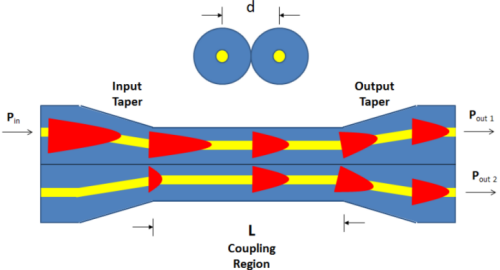
Figure 1. Schematic diagram of the structure and optical coupling distribution of the molten cone region (yellow fiber core, blue cladding, red optical energy)
Principle knowledge of FBT coupler
The intensity distribution of light passing through optical fibers is basically Gaussian distribution. That is to say, the strength is highest at the center, and the energy gradually decreases as the center approaches the core/cladding interface. It is worth noting that the tail energy of the Gaussian distributed energy slightly extends beyond the boundary between the core and the cladding. The light wave with tail energy is called a evanescent wave. Figure 2 shows the energy distribution of light waves in the cross-section of an optical fiber. The vertical dashed line represents the boundary between the fiber core/cladding. The red part represents the energy of evanescent waves.

Figure 2. Energy distribution of light transmitted in optical fibers (the red part represents the energy of evanescent waves)
In the FBT process, the cores of two parallel optical fibers are so close that evanescent waves can "leak" from one core to the other. The degree of energy exchange generated in the coupling region mainly depends on the spacing'd 'between the fiber cores and the length' L 'of the coupling region. From Figure 1, it can be observed that if the coupling length is long enough, energy can be completely coupled from one fiber to another. If its length is longer, the coupling process will continue to transfer energy back to the original fiber. By selecting the appropriate length, any given power transfer ratio can be achieved. That's why we can create 50/50 or 10/90 couplers by controlling the cone pulling process.
Let's learn about it through an example
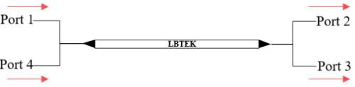
Figure 3. A 50/50 tapered coupler with a 2 × 2 port structure.
The fused taper device shown in Figure 3 is a 1550 nm 50/50 coupler. Assuming we input 1mW of 1550nm light to port 1 and also input 1mW of 1550nm light to port 4. So how much optical power can we measure at output ports 2 and 3 respectively? It is obvious that we will measure 1mW at each output port, and the light at each input port will be divided into two equal parts of 50/50.
Assuming we input 1mW to port 1 and 2mW to port 4. How large can output ports 2 and 3 be measured separately now? According to the previous conclusion, the input optical energy of each path is divided into two equal parts, so now we measure 1.5 mW at each output port (Port 1 contributes 0.5 mW, Port 4 contributes 1 mW).
Let's further analyze and still use Figure 3, a 50/50 coupler. Assuming that port 4 is now damaged (such as being cut off), a typical three port device would first make it into a 4-port, and then break and roughen the fiber optic of the 4-port to avoid the smooth cross-section from producing reflected echoes, it would become a 1x2 coupler. If we input 2mW at port 1, it is easy to know that we will ultimately measure 1mW at ports 2 and 3.
Assuming we input 1mW to port 1 and 2mW to port 4. How large can output ports 2 and 3 be measured separately now? According to the previous conclusion, the input optical energy of each path is divided into two equal parts, so now we measure 1.5 mW at each output port (Port 1 contributes 0.5 mW, Port 4 contributes 1 mW).
Let's further analyze and still use Figure 3, a 50/50 coupler. Assuming that port 4 is now damaged (such as being cut off), a typical three port device would first make it into a 4-port, and then break and roughen the fiber optic of the 4-port to avoid the smooth cross-section from producing reflected echoes, it would become a 1x2 coupler. If we input 2mW at port 1, it is easy to know that we will ultimately measure 1mW at ports 2 and 3.
Reciprocity of tapered couplers
In a standard 50/50, 2x2 coupler, if the input and output of the inverted light are reversed due to the symmetry of its structure, we can easily understand that its forward and reverse transmission have the same properties. However, when using a 1x2 coupler, people sometimes have doubts because the obvious asymmetry of the device can give people the illusion that its reverse transmission working principle will be different from forward transmission.
Continuing with the previous example of a 2x2 coupler, if light is input from the original two "output" ports 2 and 3, will the light 100% come out from port 1? Of course not, light also wants to come out from the damaged port 4. Therefore, if we only input 1mW from port 2, then only 0.5 mW will be output from port 1. Alternatively, if we input 1mW to port 2 and 2mW to port 3, we will output 1.5 mW from port 1 (with port 2 contributing 0.5mW and port 3 contributing 1mW). This energy distribution method is consistent with forward transmission. So the tapered coupler has reciprocity, and the forward and backward transmission have the same properties.
Continuing with the previous example of a 2x2 coupler, if light is input from the original two "output" ports 2 and 3, will the light 100% come out from port 1? Of course not, light also wants to come out from the damaged port 4. Therefore, if we only input 1mW from port 2, then only 0.5 mW will be output from port 1. Alternatively, if we input 1mW to port 2 and 2mW to port 3, we will output 1.5 mW from port 1 (with port 2 contributing 0.5mW and port 3 contributing 1mW). This energy distribution method is consistent with forward transmission. So the tapered coupler has reciprocity, and the forward and backward transmission have the same properties.
In summary, we need to know that a 1x2 coupler is essentially a 2x2 coupler, with only one fiber being cut and damaged (to reduce reflection from the cross-section).
Choosing the FBT Coupler that suits oneself can be considered from the following aspects:
Performance parameters
-
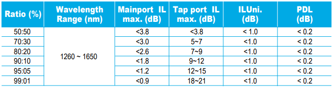
Coupling ratio: Choose the appropriate coupling ratio based on actual needs. If it is necessary to evenly distribute the optical signal to multiple ports, couplers with equal coupling ratios can be selected; If there are specific power allocation requirements, choose a coupler with a non-uniform coupling ratio.
-
Insertion loss: The lower the insertion loss, the higher the efficiency of signal transmission. When selecting, it is advisable to choose couplers with low insertion loss to ensure signal strength.
-
Additional loss: Additional loss reflects the additional energy loss of the coupler during operation. Generally speaking, the smaller the additional loss, the better.
-
Directionality: A coupler with good directionality can effectively prevent signal reverse transmission and improve system stability.
Working wavelength
-
Determine the required operating wavelength range and select the FBT coupler that matches it. Different application scenarios may require optical signals of different wavelengths, such as the commonly used 1310nm and 1550nm wavelengths in the communication field.

Environmental adaptability
-
Temperature range: Considering the temperature changes in the usage environment, choose a coupler that can work normally within the required temperature range. Some application scenarios may require working in extreme temperatures, such as outdoor environments or industrial fields.
-
Packaging form: Choose the appropriate packaging form according to the actual installation requirements. Common packaging forms include bare fiber type, tail fiber type, and modular type.


Differences between Steel Pipe Couplers and FBT Couplers
How much do you know about couplers
Related Article

How much do you know about couplers
Optical Couplers: The Silent Guardians of Signal Transmission

This article comprehensively analyzes the differences between steel pipe couplers and FBT (Fiber Optic Splice Tray) couplers in terms of their materials, structures, functions, application scenarios, installation methods, and performance characteristics. Understanding these differences is crucial for choosing the appropriate coupling device in different engineering and technical fields.
Differences between Steel Pipe Couplers and FBT Couplers
