What is the difference between FBT coupler and PLC splitter?
In optical communication systems, fiber optic splitters and fiber optic couplers, as passive components, play a crucial role in signal distribution and combination. Although they share some functional overlaps, their design principles, application scenarios, and performance characteristics differ significantly. This article will systematically analyze the differences and synergistic values between the two from the perspectives of technical principles, core functions, application scenarios, and typical cases.
I. Optical fiber splitter

1. Definition and function
An optical fiber splitter is a passive device that distributes a single optical signal to multiple output ports at a fixed ratio, with the core goal of achieving unidirectional and uniform signal distribution. For example, in FTTH (Fiber-to-the-Home) networks, a 1×32 splitter can evenly distribute the optical signal from the central office (OLT) to 32 user terminals, significantly reducing the number of trunk fibers and lowering network construction costs.
2. Technical types and characteristics
Fused Biconical Taper (FBT) Splitter:
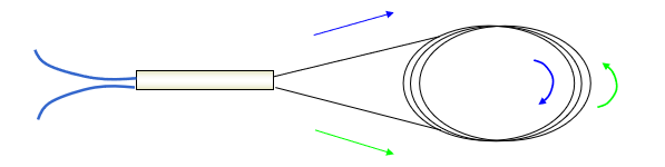
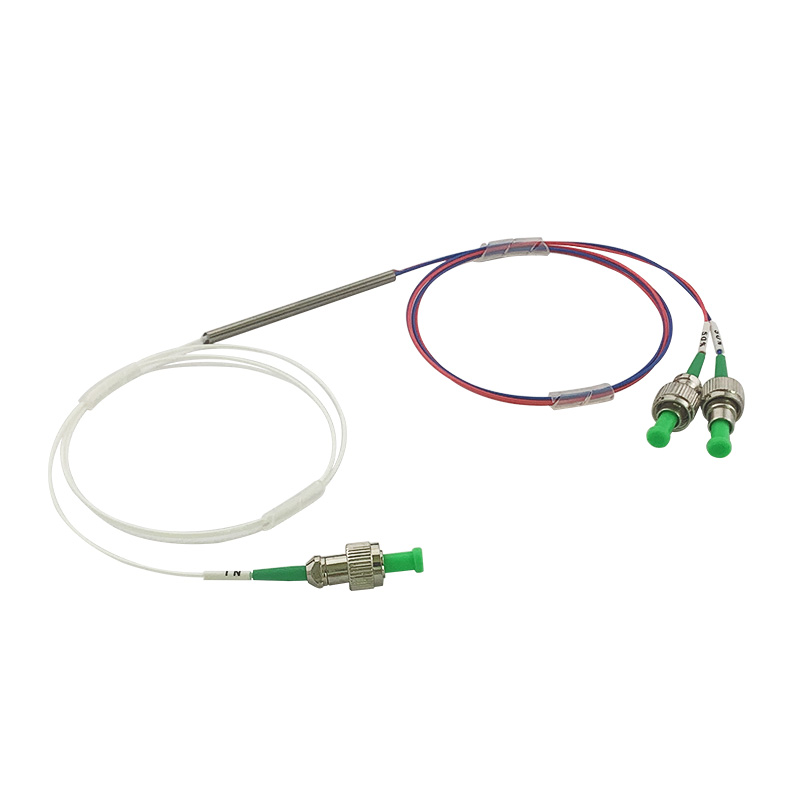
By fusing and stretching two optical fibers, optical coupling is achieved. This method boasts a simple structure and low cost, but its uniformity of the splitting ratio is poor. It is suitable for scenarios with a low number of ports (such as 1×2 and 1×4).
Planar Lightwave Circuit (PLC) Splitter:
Manufactured based on semiconductor technology, it boasts high integration and excellent uniformity in splitting ratio (within ±0.5dB), supporting high-density ports (such as 1×64, 1×128). It is the preferred solution for carrier-grade networks. Its fiber diameters (such as 250μm, 900μm, or 2mm) can accommodate different packaging needs, such as miniature modules or rack-mount installations.
3. Core advantages
Fixed splitting ratio: Ensure balanced signal strength at all output ports to avoid signal differences at the user end.
Low insertion loss: The loss at a single port of the PLC splitter can be as low as 0.3dB, ensuring the quality of long-distance transmission.
High reliability: The passive design is immune to electromagnetic interference, with a lifespan of over 25 years, making it suitable for deployment in harsh environments.
II. Optical fiber coupler

1. Definition and function
A fiber optic coupler is a multi-port device capable of both distributing signals (1×N) and combining signals (N×1). Its core value lies in enabling bidirectional transmission and dynamic scheduling of optical signals. For instance, in a Wavelength Division Multiplexing (WDM) system, the coupler can combine signals of different wavelengths into a single fiber, or separate signals to different detectors at the receiving end; in a bidirectional link, it can simultaneously support the transmission of upstream and downstream signals.
2. Technical types and characteristics
Melting coupler:
Optical coupling is achieved by melting two optical fibers, with a customizable splitting ratio (such as 30/70, 50/50), suitable for non-uniform distribution scenarios.
Cone coupler:
Low-loss coupling is achieved using a fiber taper structure, which is commonly used in sensor networks or special testing scenarios.
WDM coupler:
Based on thin-film filtering or grating technology, routing and monitoring of specific wavelength signals are achieved, such as combining 12 signals with different wavelengths in a DWDM system.
Its port configuration is flexible, such as 1×2, 2×2, 1×4, etc., supporting bidirectional communication and signal injection/extraction.
3. Core advantages
Flexible splitting ratio: The output ratio can be adjusted according to demand, adapting to diverse application scenarios.
Bidirectional transmission capability: Supports full-duplex communication, simplifies network topology design, and reduces the number of devices.
Multi-function integration: In a WDM system, signal combination, distribution, and monitoring can be simultaneously achieved, enhancing network manageability.
III. Core differences between fiber optic splitters and couplers
1. Functional direction
Fiber optic splitters specialize in unidirectional distribution, meaning they distribute signals from a single input port to multiple output ports. On the other hand, fiber optic couplers support bidirectional distribution or merging, such as merging multiple input signals into one output, distributing one signal to multiple outputs, or even achieving bidirectional transmission simultaneously.
2. Spectral ratio characteristics
The splitting ratio of a splitter is usually fixed (such as 1×8 uniform distribution), with the design goal of minimizing the signal strength difference among ports; while the splitting ratio of a coupler can be customized (such as 30/70 non-uniform distribution) to meet special requirements such as signal monitoring and power injection.
3. Typical application scenarios
Splitters are widely used in scenarios requiring equal power distribution, such as FTTH networks and CATV signal distribution; couplers are mostly used in scenarios requiring non-point-to-point connections, such as WDM systems, bidirectional links, optical power monitoring, and test and measurement devices.
4. Loss control priority
The splitter prioritizes the uniformity of the splitting ratio, followed by loss control; the coupler needs to balance the splitting ratio and loss, making the design more complex. For example, in signal monitoring scenarios, a 1×99 coupler splits 1% of the signal to the monitoring equipment, while the remaining 99% continues to be transmitted, ensuring both monitoring accuracy and minimizing main link loss.
IV. Comparison of classic application scenarios
1. PLC splitter in FTTH network
In the PON (Passive Optical Network) architecture, the 1×32 PLC splitter evenly distributes the 1550nm downstream signal from the OLT to 32 ONUs (Optical Network Units), while simultaneously combining the 1310nm upstream signal back to the OLT. Its even light distribution characteristic ensures that the signal strength difference received by all users is less than 0.5dB, meeting carrier-grade service quality requirements.
2. Coupler in WDM system
In a Dense Wavelength Division Multiplexing (DWDM) system, a coupler combines signals from 12 different wavelengths (such as 1528nm~1561nm) into a single optical fiber for transmission, and separates the signals at the receiving end through a demultiplexer. Additionally, the coupler can also be used for pump laser injection in an Optical Amplifier (EDFA), allowing precise control of signal gain by adjusting the splitting ratio.
3. Coupler in testing and measurement
In optical power monitoring scenarios, a 1×99 coupler diverts 1% of the signal to a monitoring device (such as an optical spectrometer), while the remaining 99% of the signal continues to be transmitted to the main link. This asymmetric splitting design not only ensures monitoring accuracy but also avoids signal attenuation in the main link caused by optical splitting.
V. Collaborative Value: Building Efficient Optical Networks
Fiber optic splitters and couplers often work together in optical communication networks:
The splitter is responsible for the balanced distribution of signals in the backbone network, reducing the cost of fiber deployment;
The coupler facilitates flexible scheduling and monitoring of signals, enhancing network manageability.
For example, in a 5G fronthaul network, a PLC splitter distributes signals from an AAU (Active Antenna Unit) to multiple RUs (Radio Frequency Units), while a coupler is used for signal injection and performance monitoring of the CPRI link, jointly ensuring low-latency and high-reliability data transmission.
Conclusion
Fiber optic splitters and couplers, as the "right and left hands" of optical communication systems, respectively embody the core values of balanced distribution and flexible scheduling, meeting diverse application needs through differentiated designs. With the rapid development of FTTx, 5G, and data centers, their high-density, low-loss, and multi-functional integration characteristics will become a key force driving the evolution of optical networks towards higher efficiency and lower costs.
Optical Couplers: The Silent Guardians of Signal Transmission
Related Article