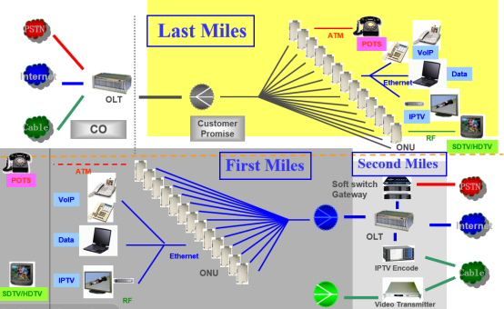
Why Your Optical Splitter Can't Guarantee the Transmission Efficiency of Optical Signals?
author: Lucas
2024-11-15
Insertion Loss Problem
1. Definition and Impact
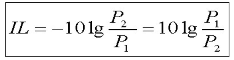
Insertion loss is an important parameter of the optical splitter. When an optical signal passes through the splitter, due to factors such as the material properties of the splitter itself and the quality of fiber splicing, a certain amount of optical power will be lost. High insertion loss can lead to weak output optical signals, as shown in [Figure 1: Diagram of Insertion Loss Effect]. This can affect the normal operation of subsequent optical equipment. For example, in a fiber - access network, if the insertion loss of the splitter is too high, the optical modem at the user end may receive optical power below the normal working threshold, resulting in unstable network connections or even the inability to connect.
2. Causes of Insertion Loss
- Material Quality: Low - quality materials used in the manufacturing of the splitter can increase absorption and scattering of light within the device.
- Splicing Issues: Poor fiber - to - fiber splicing during the production process can introduce additional losses. [Figure 2: Image of Fiber Splicing in an Optical Splitter]
Splitting Ratio Deviation
1. Description of the Problem
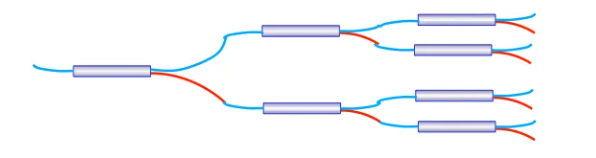
The splitting ratio of an optical splitter is designed to distribute optical signals according to specific requirements. But in practice, there may be deviations from the nominal splitting ratio during production and use. This could be due to manufacturing process errors or device aging. Deviations in the splitting ratio can affect the accuracy of optical signal distribution. In applications that require precise splitting, such as networks with strict optical power budgets, this can cause serious problems. For instance, in a 1:4 splitting ratio splitter that is nominally designed, in actual use, due to small differences in the internal structure, the splitting ratio of one of the output ports may deviate from the design value, resulting in either too high or too low optical power at that port, thereby affecting the performance of the equipment connected to it.
2. Effects on Signal Transmission
- Unbalanced Power Distribution: Different output ports may have unequal optical power, leading to inconsistent performance of connected devices.
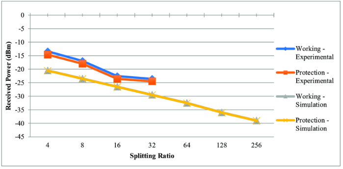
- Network Instability: In a network relying on accurate splitting, this can cause fluctuations in signal strength and overall instability. [Figure 3: Graph Showing the Impact of Splitting Ratio Deviation on Signal Strength]
Insufficient Isolation
1. Definition and Consequences
Isolation refers to the degree of isolation of optical signals between the output ports of the splitter. If the isolation is insufficient, the optical signal from one output port may leak to other output ports, causing crosstalk. This crosstalk degrades signal quality. In wavelength - division multiplexing (WDM) systems, it can cause interference between different wavelength signals. For example, in a video surveillance system using an optical splitter for signal transmission, insufficient isolation can cause interference between signals from different cameras, resulting in snow - like or striped interference patterns on the screen.
2. Reasons for Insufficient Isolation
- Design Flaws: Inadequate design of the internal structure of the splitter may lead to poor isolation.
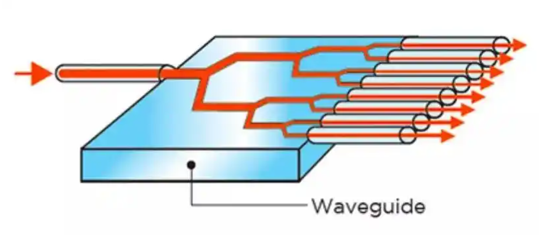
- Manufacturing Tolerances: Variations within the manufacturing process can affect the isolation performance. [Figure 4: Schematic of Isolation Structure in an Optical Splitter]
Physical Damage
1. Fiber Breakage
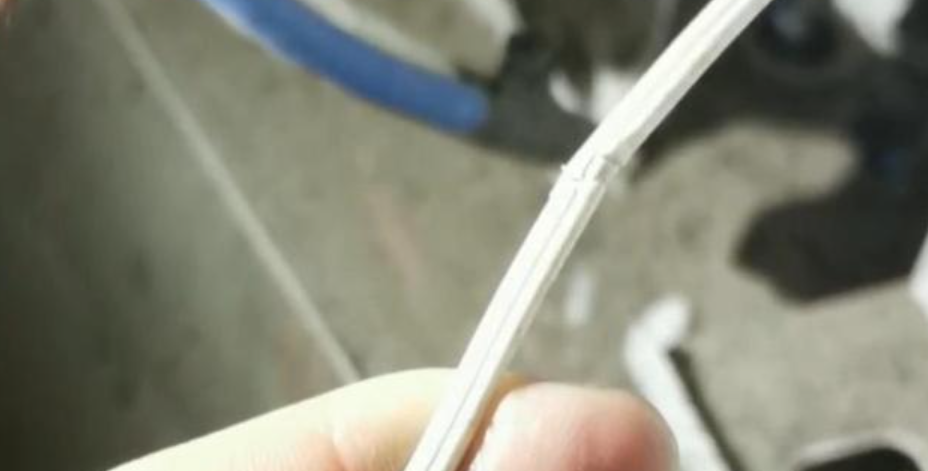
- Fiber breakage is a common problem. The fiber part of the optical splitter is relatively fragile. During installation and maintenance, if subjected to excessive bending, stretching, compression, or if it is in a harsh environment for a long time (such as drastic temperature changes, high humidity, or the presence of chemical corrosive substances), the fiber may break. Fiber breakage will interrupt the optical signal transmission, and the entire splitter will not work properly. For example, during the construction site of an optical splitter, if the construction personnel bend the fiber with a radius that is too small during laying, it is easy to cause the core of the fiber inside to break, making the optical signal unable to pass through this part of the fiber. [Figure 5: Image of a Broken Fiber in an Optical Splitter]
2. Port Damage
- The ports of the splitter, including the input and output ports, may be damaged during frequent plugging and unplugging of fiber connectors or when subjected to collisions. Port damage can lead to poor connection of optical signals, unstable optical power, etc. For example, if during maintenance, the fiber plug used does not match the port of the splitter and is forcibly plugged in or unplugged, it may scratch the fiber alignment structure inside the port, reducing the coupling efficiency of the optical signal and affecting the transmission of the optical signal. [Figure 6: Image of a Damaged Port of an Optical Splitter]
Compatibility Issues
1. Incompatibility with Fiber Types
- Optical splitters are designed for either single - mode or multi - mode fibers. If a single - mode fiber is connected to a multi - mode fiber splitter or vice versa, the transmission efficiency of the optical signal will be greatly reduced or even unable to transmit normally. This is because single - mode and multi - mode fibers have different core diameters, numerical apertures, and other parameters, and have different requirements for the transmission mode of optical signals. For example, during an upgrade of the internal network of a data center, if a single - mode fiber is mistakenly connected to an originally multi - mode fiber splitter, it will cause failures in the optical communication between servers, and the data transmission error rate will increase significantly.
2. Incompatibility with Optical Equipment
- Different manufacturers' optical equipment may have different specifications for parameters such as the wavelength range and power requirements of optical signals. If the output optical signal characteristics of the optical splitter do not match the connected optical equipment, problems such as the equipment's inability to recognize the signal and abnormal operation will occur. For example, some early - stage optical network terminal equipment may only support the reception of optical signals within a specific wavelength range, and if the newly installed optical splitter outputs optical signals outside this range, the terminal equipment will not be able to work normally.
Conclusion
To ensure the efficient transmission of optical signals by the optical splitter, it is necessary to pay attention to these potential problems, from performance - related issues to physical damage and compatibility issues. By understanding and addressing these problems, we can improve the performance of the optical splitter in the optical communication system.
https://www.alibaba.com/product-detail/1x2-fiber-optic-PLC-Splitter-with_62255585466.html?spm=a2747.product_manager.0.0.7b1371d2A93f81https://www.alibaba.com/product-detail/1x2-fiber-optic-PLC-Splitter-with_62255585466.html?spm=a2747.product_manager.0.0.7b1371d2A93f81
PLC and FBT optical splitter: shining stars in the field of optical communication
-Optical splitter: a brilliant bridge connecting the digital world-
Related Article