What is AWG? Analysis of Core Components in DWDM System

1、 What is AWG?
The full name of AWG is Arrays Waveguide Grating. It is an optical device based on planar lightwave circuit technology, which can be simply understood as compressing the diffraction grating in traditional optics onto a small chip through semiconductor technology.
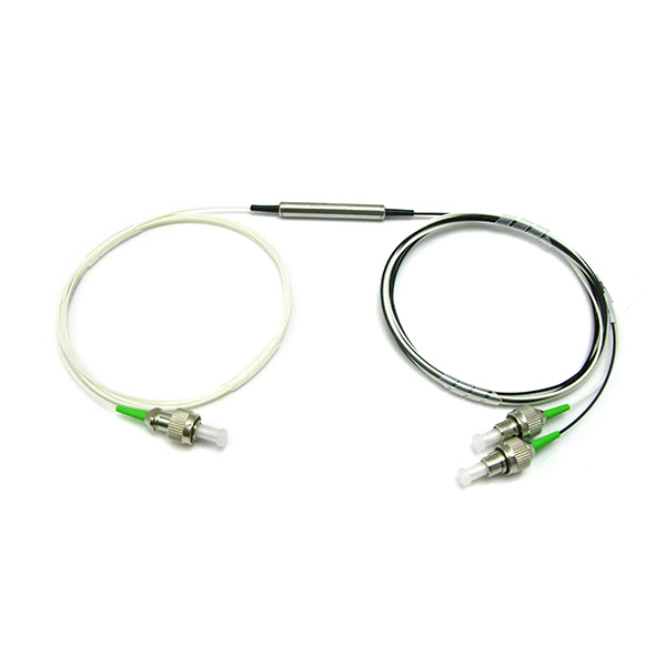
From the appearance, AWG is usually a small rectangular box with a size of approximately a few centimeters square. One side of the box extends an input fiber, while the other side extends dozens of output fibers, arranged in a neat array. It is precisely this "one in, multiple out" appearance feature that intuitively reflects its core function.
The core function of AWG is very pure: to act as a multiplexer at the transmitting end, combining multiple optical signals of different wavelengths into one optical fiber for transmission; At the receiving end, a splitter is used to separate the composite optical signal in an optical fiber into different ports according to wavelength. It is this seemingly simple function that supports the infrastructure of the entire DWDM system.
2、 Internal structure of AWG
A typical AWG consists of five core components, each with its irreplaceable function:
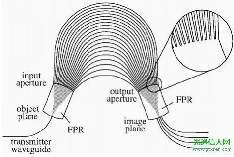
The first part is the input waveguide. This is the "entrance" of AWG, carrying composite light containing multiple wavelengths into the chip. It is usually a coupling interface between a standard single-mode fiber and a chip.
The second part is the input star coupler. The function of this area is to disperse the input light and evenly distribute it to all the array waveguides behind it. This process is wavelength independent, and all wavelengths enter each waveguide 'equally'.
The third part is the array waveguide region. This is the core area of AWG, composed of hundreds of waveguides arranged in parallel. The length of these waveguides increases precisely, such as the first length L, the second length L+Δ L, the third length L+2 Δ L, and so on. This small length difference Δ L is usually in the micrometer range, but it determines the wavelength resolution of the entire device.
The fourth part is the output star coupler. Light from various array waveguides converges here, resulting in multi beam interference. According to the principle of interference, light of different wavelengths will form focal points at different positions.
The fifth part is the output waveguide array. These focal points are precisely aligned with the entrance of the output waveguide, and each wavelength of light enters its corresponding output waveguide, ultimately leading out of the chip through optical fibers.
3、 Working principle of AWG
From a professional technical perspective, the design of AWG relies on the Roland circle and concave grating structure:
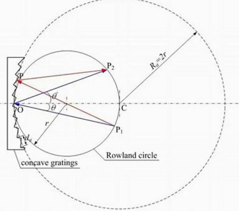
The radius of the Roland circle is r, and the curvature radius of the concave grating is R=2r. The two are inscribed and the Roland circle passes through the center of the grating.
Through optical path analysis and approximation, it can be concluded that the light emitted from any point on the Roland circle remains focused on the Roland circle after diffraction by a concave grating, with different diffraction orders corresponding to different diffraction angles;
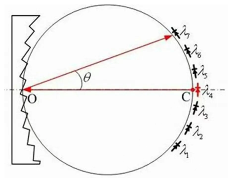
The light signal emitted from point C on the Roland circle in the figure is reflected and diffracted by a concave grating, and different wavelengths are focused on different points on the Roland circle.
For AWG, waveguide C is equivalent to an input waveguide, and the optical signal input at that position is reflected, diffracted, and focused into different output waveguides through the array waveguide. The positions of λ 1- λ 7 correspond to different output waveguides.
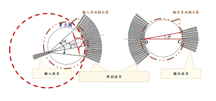
The input/output star coupler of AWG adopts a structure similar to concave reflective gratings and Roland circles. The input waveguide and output waveguide respectively restrict and conduct light.
The ports of the input/output waveguide are located on the circumference of the Roland circle, while the array waveguide is located on the circumference of the concave grating, but the array waveguide is equivalent to a transmissive grating.
The input star coupler and the output star coupler form a mirror relationship, and the optical signal emitted by the input waveguide is diffracted by the array waveguide, focusing different wavelengths onto different output waveguides.
Introducing a large optical path difference at the array waveguide enables the grating to operate in high-order diffraction, improving the grating resolution.
4、 Key performance parameters of AWG
To evaluate the performance of an AWG, the following core indicators should be considered:
The number of channels refers to the number of wavelengths supported by AWG. The mainstream commercial products are 40 waves, 48 waves, 80 waves, and 96 waves, and high-end products can reach more than 120 waves. The more channels there are, the larger the system capacity.
Channel spacing refers to the wavelength or frequency difference between adjacent channels. The mainstream standards are 100GHz and 50GHz, and a 50GHz interval can double the number of channels. A narrower 25GHz interval is used for ultra-high density systems.
Insertion loss refers to the power loss of light after passing through AWG. The typical value is between 2.5dB and 5dB, and the more channels there are, the slightly higher the loss. The smaller the insertion loss, the more advantageous it is for the system's optical power budget.
Adjacent channel isolation refers to the ability to suppress crosstalk between adjacent wavelengths. Typical requirement is ≥ 25dB, the higher the value, the better. If the isolation is not sufficient, signals from adjacent channels will interfere with each other, resulting in an increase in bit error rate.
Non adjacent channel isolation refers to the ability to suppress crosstalk between other non adjacent wavelengths. Typical requirement is ≥ 30dB, the higher the better.
Polarization related loss refers to the difference in loss when light of different polarization states passes through an AWG. The typical requirement is ≤ 0.5dB. The smaller the size, the less sensitive the device is to polarization and the better the system stability.
The central wavelength accuracy refers to the deviation between the actual channel and the ITU-T standard wavelength. The typical requirement is within ± 0.05nm, and the smaller the deviation, the better the interoperability with other devices.
Among all parameters, isolation is the most critical, as it directly determines the level of crosstalk that the system can tolerate.
5、 Main classifications of AWG
According to different application scenarios and designs, AWG can be divided into multiple types:
Classified by channel spacing, there are 100GHz AWG, 50GHz AWG, and 25GHz AWG. The 100GHz interval is wide, the number of channels is small, and the cost is low; 50GHz is currently the mainstream, achieving a balance between the number of channels and cost; 25GHz is used for ultra large scale DWDM systems, which require extremely high manufacturing accuracy.
Classified by temperature characteristics, there are two types: thermal AWG and thermal control AWG. Non thermal AWG with built-in temperature compensation structure, no electrical power consumption required, suitable for passive scenarios such as urban access networks. Thermally adjustable AWG with heater can accurately lock the wavelength, suitable for scenarios with high stability requirements, such as core backbone networks.
Classified by function, there are multiplexing AWG, multiplexing AWG, and multiplexing/demultiplexing integrated AWG. Composite AWG is used for the transmitting end, with multiple inputs and one output; Wavelength division AWG is used for the receiving end, with one input and multiple outputs; The integrated AWG can work in both directions, and the same device can be used for transmitting and receiving simultaneously.
6、 The role of AWG in DWDM system
In a typical point-to-point DWDM system, AWG plays an indispensable role:
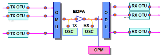
At the transmitting end, multiple optical transmitters emit optical signals of different wavelengths, with each transmitter corresponding to a specific wavelength. These optical signals enter different input ports of the AWG multiplexer. AWG efficiently merges them together, outputting from a single output port and transmitting them through a single fiber optic cable.
During transmission, the merged composite light may be compensated for by optical amplifiers or extended by repeaters, but all wavelengths are always transmitted in parallel on the same fiber.
At the receiving end, the composite light enters the AWG splitter. AWG precisely separates them based on wavelength, with each wavelength output from its own output port and sent to the corresponding optical receiver for processing.
This process may seem simple, but it relies on the high selectivity of AWG towards wavelengths. If the performance of AWG is insufficient, crosstalk may occur between different wavelengths, or excessive loss may result in incorrect signal reception, causing the entire system to malfunction.
7、 Summary
Array waveguide grating is an optical chip based on planar optical wave circuit technology. Its core function is to combine multiple optical signals of different wavelengths into one optical fiber for transmission at the transmitting end, and separate the composite light into different ports according to wavelength at the receiving end. It has become the core component of DWDM systems because it is currently the only technology that can simultaneously, efficiently, and cost effectively process dozens or even hundreds of wavelengths, making high-density wavelength division multiplexing systems such as 40 wave, 80 wave, and 96 wave from theory to reality. The main technical indicators for evaluating AWG include the number of channels, channel spacing, insertion loss, isolation, etc. Among them, isolation is the most critical parameter, which directly determines the crosstalk control level of the system. Compared with other technologies such as thin film filters, AWG has significant advantages such as multiple channels, uniform loss, high integration, good reliability, and low cost. Therefore, it is widely used in various fields such as DWDM systems, PON networks, data center interconnection, optical sensing, optical testing instruments, quantum communication, etc. In the future, AWG is developing towards narrower spacing, wider frequency band, lower loss, smaller size, and higher integration.
About ZG Technology
Founded in 2005, ZG is a leading OEM/ODM and solution provider for passive optical components in the global industry, focusing on the research and development, manufacturing, sales, and service of passive basic components for optical communication. The company's main products are four core optical passive basic devices, including optical fiber jumper (high-density cabling in data center), WDM wavelength division multiplexer, PLC optical splitter, MEMS optical switch, which are widely used in fields such as fiber to the home, 4G/5G mobile communication, Internet data center, and national defense communication.
What is the difference between WDM and OTN?
Related Article