MPO Fiber Connector Complete Guide: Types, Polarity, and Data Center Applications
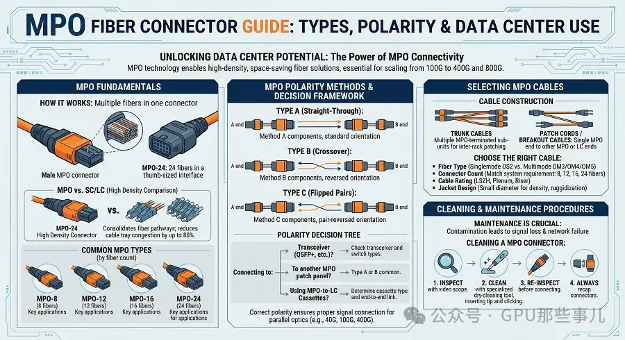
A hyperscale data center once faced a crisis: 10,000 new servers needed network connectivity, but only 40% of planned fiber pathway capacity remained, and the existing ceiling structure could not accommodate additional cable trays. The solution was not to create more space but to adopt MPO connectors. The team consolidated 24 fibers into a thumb-sized connector, completing the entire deployment without pathway modification and cutting installation time by 80%.
This is the power of Multi-fiber Push-On (MPO) technology.
As data centers transition from 100G to 400G and 800G, MPO connectors have become the standard interface for high-speed parallel optical systems. Network engineers must master MPO technology.
This guide covers everything you need to know about MPO fiber connector systems, including technical specifications, polarity methods and selection frameworks, and cable type guidance, providing essential knowledge for both new projects and existing system troubleshooting.

Contents:
1. What Is an MPO Connector?
1.1 Key Technical Specifications
1.2 MPO Connector Components
2. MPO vs. MTP: Detailed Differences
2.1 Core Differences
2.2 Side-by-Side Performance Comparison
2.3 Standard MPO Selection Criteria
2.4 MTP Selection Criteria
3. MPO Connector Types and Configurations
3.1 Fiber Count Specifications
3.2 Male/Female and Keying
3.3 Polish Types
4. MPO Polarity Methods Explained
4.1 Type A Polarity — Straight-Through
4.2 Type B Polarity — Reversed / Flipped
4.3 Type C Polarity — Pairwise Flipped
5. MPO Cable Types and Applications
5.1 Trunk Cables
5.2 Breakout / Fan-out Cables
5.3 Patch Cables
5.4 Data Center Architecture Applications
6. MPO in High-Speed Optical Transceivers
6.1 40G Applications
6.2 100G Applications
6.3 400G Applications
6.4 800G Applications
6.5 1.6T and Beyond
6.6 OSFP and MPO Integration
--------
- What Is an MPO Connector?
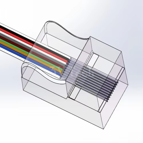
1.1 An MPO connector is a high-density fiber connector that terminates multiple fibers in a single precision-molded, glass-filled polymer MT ferrule. Its space-saving rectangular design supports 8 to 72 fibers, far surpassing traditional LC or SC connectors that accommodate only 1 or 2 fibers.
MPO connectors comply with international standards IEC 61754-7 and TIA-604-5 (FOCIS 5), ensuring interoperability among products from different manufacturers. This standardization makes MPO the cornerstone of modern high-density fiber infrastructure.
1.2 MPO Connector Components
1) Ferrule: The MT (Mechanical Transfer) ferrule is precision-molded to align multiple fibers in a linear array. A standard MPO-12 ferrule precisely positions 12 fibers in a single row.
2) Guide Pins: Male connectors feature two metal alignment pins protruding from the ferrule face, while female connectors have corresponding holes. Guide pins ensure precise fiber alignment during mating, which is critical for optical performance.
3) Keying Mechanism: The housing includes a raised plastic key that ensures proper orientation and prevents reverse insertion. Fiber mapping and polarity depend on whether the connector is oriented key-up or key-down.
4) White Dot Indicator: A marking on the connector body indicates the position of fiber #1, essential for polarity management and troubleshooting.
- MPO vs. MTP: Detailed Differences
MPO and MTP are often used interchangeably, but important distinctions exist. Understanding these differences helps in selecting the right connector for specific performance requirements and budget.
2.1 Core Differences
1) MPO (Multi-fiber Push-On): A generic industry standard compliant with IEC 61754-7. Any manufacturer can produce MPO connectors that meet this specification.
2) MTP (Multi-fiber Termination Push-on): A trademarked, enhanced product exclusively from US Conec. MTP connectors feature tighter tolerances and additional features, delivering performance beyond standard MPO.
3) Key Takeaway: All MTP connectors can be used as MPO connectors, but not all MPO connectors meet MTP performance levels.
2.2 Standard MPO Selection Criteria
- Budget-sensitive deployments
- Enterprise networks with moderate density requirements
- Applications with generous insertion loss budgets
- Installations with infrequent connector mating cycles
- Main Distribution Area to Intermediate Distribution Area links and campus backbones
2.3 MTP Selection Criteria
- Hyperscale data centers with strict loss budgets
- High-speed parallel optics (100G, 400G, 800G)
- Environments requiring frequent reconfiguration
- Links where every decibel of loss is critical
- Long-term infrastructure where reliability is paramount
The final choice depends on link loss calculations. In complex data center architectures with multiple connection points, premium MTP connectors help preserve signal strength and reduce troubleshooting.
- MPO Connector Types and Configurations
3.1 MPO connectors come in various configurations. Selecting the correct type ensures compatibility with transceivers, switches, and cabling infrastructure.

1) MPO-8: 8 fibers (4 Tx + 4 Rx) for 40G/100G SR4. Uses the outer positions of a 12-fiber ferrule, leaving the middle fibers unused.
2) MPO-12: The most versatile format, supporting multiple applications. The standard solution for 40G/100G SR4 and widely used in trunk cabling. In SR4 applications, the middle 4 fibers are unused, preserving upgrade flexibility.
3) MPO-16: The standard for 400G SR8 and 800G SR8. Native 16 fibers (8 Tx + 8 Rx) with 50G or 100G per lane. Compared to using MPO-24 for 8-lane applications, there is no wasted fiber.
4) **MPO-24:** Two rows of 12 fibers each, offering the highest density. Supports 100G SR10 (10 lanes), 120G applications, or three simultaneous 40G links. Commonly used for high-density trunk cables to ensure future adaptability.
3.2 Male/Female and Keying
1) Male Connector: Features two guide pins protruding from the ferrule. Primarily used for cable-to-cable connections and trunk extensions.
2) Female Connector: Has two holes to receive guide pins. Used for mating with equipment ports, transceivers, and patch panels.
3) Critical Rule: Equipment ports (switches, transceivers) are male; cables connecting directly to equipment must be female.
4) Key Orientation:
- Key-Up: Key is at the top when viewing the connector face.
- Key-Down: Key is at the bottom when viewing the connector face.
Key orientation affects fiber mapping and must align with the polarity method.
3.3 Polish Types
1) UPC (Ultra Physical Contact): Slight 0° radius polish. Used for multimode fiber (OM3/OM4/OM5). Standard for 40G/100G/400G SR applications.
2) APC (Angled Physical Contact): 8° angled polish. Used for single-mode fiber. Provides return loss ≥60 dB. Required for single-mode 400G/800G DR/FR/LR applications.
3) Compatibility Warning: Never mix APC and UPC connectors. An APC angled ferrule will damage a UPC connector and cause high loss.
In high-speed transceiver connections, MPO connectors directly interface with OSFP transceivers for 800G applications.
- MPO Polarity Methods Explained
Polarity management ensures the correct connection between transmit (Tx) and receive (Rx) fibers. The most common issue in MPO deployments is polarity errors, which prevent links from activating.
MPO systems use three standardized polarity methods defined by TIA-568.3-D. Understanding how each works is essential to avoid installation mistakes.

4.1 Type A Polarity — Straight-Through
1) Configuration: Fiber 1 to Fiber 1, Fiber 2 to Fiber 2 ... Fiber 12 to Fiber 12. No fiber crossover.
2) Adapter Orientation: Key-Up to Key-Down flips the connector orientation while maintaining straight-through mapping.
3) Best Applications:
- Modular cassette deployments
- Smooth upgrade paths (10G → 40G → 100G)
- Simple point-to-point links
- Environments requiring maximum flexibility
4) Advantages: Simplest trunk manufacturing, widest compatibility, easiest long-term evolution.
4.2 Type B Polarity — Reversed / Flipped
1) Configuration: Fiber 1 to Fiber 12, Fiber 2 to Fiber 11. Complete reversal of the entire fiber array.
2) Adapter Orientation: Key-Up to Key-Up (no flip). Reversed mapping ensures Tx connects to Rx.
3) Best Applications:
- Direct parallel optic links (40G/100G/400G/800G SR/DR)
- Leaf-spine data center architectures
- High-speed transceiver direct-attach links
- Modern data center deployment standard
4) Critical Notification: Type B polarity is required for parallel optics. QSFP+/QSFP28/QSFP-DD/OSFP transceivers all demand this polarity. Using Type A for parallel optics results in Tx-to-Tx connections and non-functional links.
4.3 Type C Polarity — Pairwise Flipped
1) Configuration: Adjacent fibers flipped in pairs (1↔2, 3↔4, 5↔6 ...).
2) Adapter Orientation: Key-Up to Key-Down with pairwise flip.
3) Best Applications:
- MPO to LC duplex breakout systems
- Specific legacy duplex applications
- Rarely used in modern parallel optics
- MPO Cable Types and Applications
MPO cables come in several types suited for different deployment scenarios. Understanding the differences ensures correct architecture selection.
5.1 Trunk Cables
1) Description: Multi-fiber cables with MPO connectors on both ends, available in 8, 12, 16, 24, and 48-fiber configurations.
2) Applications:
- Backbone connections between distribution areas
- MDF to IDF links
- Data center row-to-row connections
- Campus backbone cabling
3) Advantages:
- High fiber count in a single cable reduces pathway congestion
- Pre-terminated for rapid deployment
- Factory polish ensures consistent quality
4) Specifications to Consider:
- Riser/LSZH jacket ratings
- Single-mode (OS2) vs. Multimode (OM4/OM5)
- Pulling eye options for installation
5.2 Breakout / Fan-out Cables
1) Description: One end is MPO, the other end breaks out into individual connectors (typically LC duplex).
2) Common Configurations:
- MPO-8 to 4×LC Duplex (40G to 4×10G)
- MPO-12 to 6×LC Duplex (100G to 6×10G or 3×40G)
- MPO-24 to 12×LC Duplex (High-density server connectivity)
3) Applications:
- Connecting high-speed switch ports to lower-speed servers
- 100G to 25G server connections
- Transitioning from MPO infrastructure to LC-based equipment
4) Critical Note: Breakout cable polarity must match the infrastructure polarity (typically Type B).
5.3 Patch Cables
1) Description: Short MPO-to-MPO cables for intra-rack device interconnection.
2) Applications:
- Switch-to-switch connections in leaf-spine architectures
- Device interconnect within the same rack
- Patch field connections
3) Length: Typically 1–5 meters, optimized for rack-level connections.
5.4 Data Center Architecture Applications
1) Leaf-Spine Topology: MPO trunks form the spine layer, connecting leaf switches across different racks. MPO-24 trunks are used for multi-100G/400G spine connections.
2) Top-of-Rack (ToR) Deployments: MPO patch cables connect ToR switches to spine switches. Short 1–3 meter lengths reduce cabling congestion.
3) End-of-Row (EoR) Deployments: MPO trunks run from EoR switches to patch panels in server racks, where they transition to LC for connection to individual servers.
4) Upgrade Strategy: MPO infrastructure supports speed upgrades without recabling. An MPO-12 trunk carrying 40G today can support 100G, 400G, or 800G by simply changing the transceivers.
- MPO in High-Speed Optical Transceivers
MPO connectors serve as the physical interface for parallel optic transceivers from 40G up to 800G and beyond. Understanding these connections helps in designing scalable infrastructure.
6.1 40G Applications
1) 40GBASE-SR4: 8 fibers (4 Tx + 4 Rx), 10 Gbps per lane. Uses MPO-8 or MPO-12 (outer 8 fibers).
2) Deployment Tip: MPO-12 infrastructure supports 40G SR4 while keeping 4 fibers available for future use.
6.2 100G Applications
1) 100GBASE-SR4: 8 fibers, 25 Gbps per lane. Compatible with MPO-8/MPO-12.
2) 100GBASE-SR10: 20 fibers, 10 Gbps per lane. Requires MPO-24.
3) 100GBASE-DR4: Single-mode, 500-meter reach. Requires MPO-12 with APC polish.
6.3 400G Applications
1) 400GBASE-SR8: 16 fibers, 50 Gbps per lane. Native MPO-16 or dual MPO-12 (8 fibers each).
2) 400GBASE-DR4: 8 fibers, 100 Gbps per lane. Single-mode MPO-12 APC.
3) 400GBASE-SR16: 16 fibers, 25 Gbps per lane. MPO-16.
4) Key Decision: For new 400G deployments, prefer MPO-16 over dual MPO-12. MPO-16 avoids the 4-fiber waste inherent in using MPO-12 for 8-lane applications.
6.4 800G Applications
1) 800GBASE-SR8: 16 fibers, 100 Gbps per lane. Requires MPO-16.
2) 800GBASE-DR8: 16 fibers, 100 Gbps per lane. Single-mode MPO-16 APC.
3) Infrastructure Impact: 800G switches require MPO-16 ports or MPO-24 channel aggregation. Plan new deployments with MPO-16/MPO-24 to support 800G upgrades.
6.5 1.6T and Beyond
1) Emerging 1.6T standards will use 16 fibers × 200 Gbps or 32 fibers × 100 Gbps. MPO-24 and next-generation MPO-32 will support these speeds.
2) Strategic Implication: Deploying MPO-24 infrastructure today enables seamless upgrades to 1.6T without recabling.
6.6 OSFP and MPO Integration
The OSFP (Octal Small Form-factor Pluggable) transceiver for 800G/1.6T applications uses MPO as its standard interface:
- 800G OSFP: MPO-16
- 1.6T OSFP: MPO-16 (200G per lane) or MPO-32 (100G per lane)
This binding between MPO infrastructure and next-generation transceivers makes MPO expertise an essential skill for modern network architects.
Technical White Paper: Outlook for 2026, Top 10 Technological Evolution Trends in the Optical Communication Industry