Collimator Manufacturing Process
author: Jocelin
2024-10-14
Collimator Manufacturing Process
Definition: A device that collimates light coming out of an optical fiber, or emits collimated light into an optical fiber.
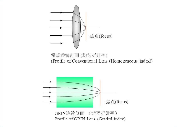
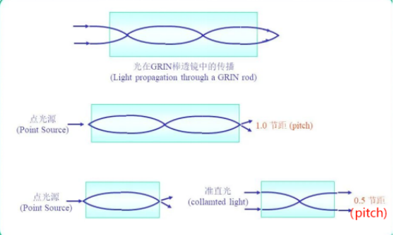
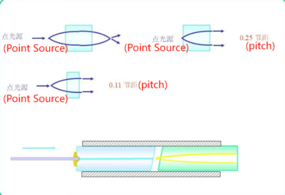
Often times, it is necessary to convert the output light from optical fibers into a collimated beam in free space. In theory, using a collimating lens (as shown in Figure 1) can meet this requirement. However, the lens requires that the distance between the fiber optic port and it be fixed, approximately equal to its focal length. In practice, using a fiber collimator is more convenient. There are two different types of fiber collimators:
one is a collimator that can be directly in contact with bare fiber. This is a cheap and simple method, but this collimator is usually permanently connected to the fiber optic cable. There is a mechanical cross-section between another type of fiber collimator and optical connector, such as FC or SMA type; Usually not used for bare fiber optics. This collimator can be easily installed or removed from fiber optic cables with connectors.
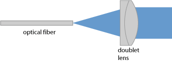
Figure 1: A lens can collimate the output light of a fiber or emit a collimated beam into the fiber.
Manufacturing Process
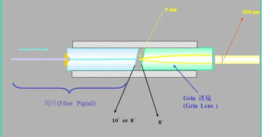
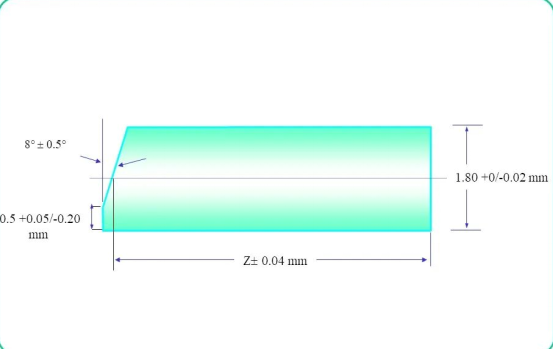
Note: Slopes and coatings are commonly used to reduce return loss.
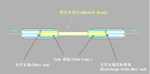
Benefits:
1. Improve the coupling efficiency between optical fibers or between optical fibers and devices.
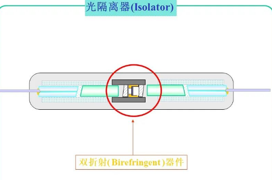
2. Other devices can be inserted into the collimated beam between two lenses to form other devices, such as inserting birefringent materials to form an optical isolator.
1. Improve the coupling efficiency between optical fibers or between optical fibers and devices.
2. Other devices can be inserted into the collimated beam between two lenses to form other devices, such as inserting birefringent materials to form an optical isolator.
Collimator calibration
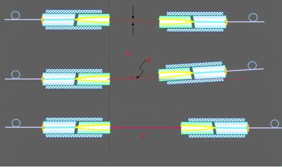
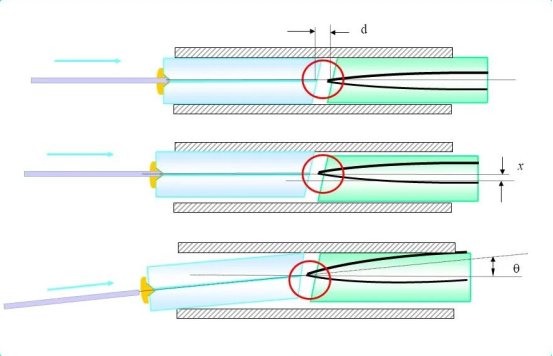
During the assembly process, standard collimators need to be used to calibrate the collimators in production, which poses a coupling problem between the two collimators. The factors that affect the coupling loss between the two fiber collimators are: off-axis distance x angle deviation 0, axial spacing d. Normally:
1. Coupling loss is highly sensitive to angle deviation of 0; Usually, when the deviation angle is 0.1 °, it can reach 5.7dB. Therefore, when combining fiber collimators, the angle is the main adjustment object.
2. When x is within a certain range, the coupling loss is insensitive to x; When x exceeds this range, the coupling loss is almost linearly related to x. 3. The coupling loss is insensitive to a certain range of d, and only gradually increases beyond this range. Generally, when the axial spacing d is less than 30mm, the coupling loss is very small; Beyond this range, gradually increase in size.
1. Coupling loss is highly sensitive to angle deviation of 0; Usually, when the deviation angle is 0.1 °, it can reach 5.7dB. Therefore, when combining fiber collimators, the angle is the main adjustment object.
2. When x is within a certain range, the coupling loss is insensitive to x; When x exceeds this range, the coupling loss is almost linearly related to x. 3. The coupling loss is insensitive to a certain range of d, and only gradually increases beyond this range. Generally, when the axial spacing d is less than 30mm, the coupling loss is very small; Beyond this range, gradually increase in size.
About PIgtail Assembly
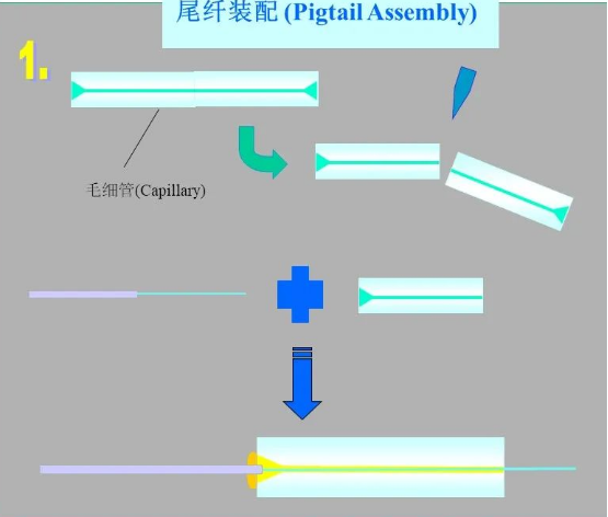
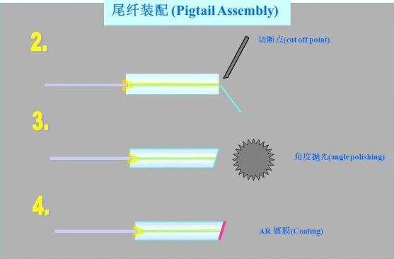
We provide comprehensive technical consultation to assist clients in evaluating the application value of Collimator Manufacturing Process. Welcome to contact our engineering team to learn more about product details and successful cases, and explore the infinite possibilities of optical communication technology together. Welcome to our website www.optical-solution.com and visit through john@optical-solution.com contact us.
Fiber Optic Transceiver: Lightspeed Connection, Endless Possibilities!
What Are Everyday Uses For Fiber Optics?